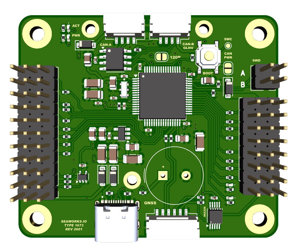
VSP driver for DroneCAN (SKU: 1673)
It is built around CAN communication as its core feature. This means it relies primarily on Controller Area Network (CAN) to connect and communicate with other devices and sensors. Using CAN allows for reliable and efficient data exchange, even in complex networks. It also simplifies the vehicle’s wiring and makes debugging easier.
The following datasheet applies universally to all versions. However, different variations in quality and grades are available, which may affect the intended usage.
A single VSP driver module can operate 2 Voith-Schneider propellers (4x servos, 2x ESC, 2x RPM sensors) and provides 8 more configurable auxiliary PWM outputs for servos. It can also serve as an interface for RC receivers, relaying signals to the autopilot with support for most common protocols including S-BUS. Additionally, a 6‑pin GNSS connector allows GNSS/GPS receivers to be routed to the autopilot, and a high-precision voltage sensor sends PWM pin voltage telemetry to the autopilot.
An autopilot is needed to operate this module. We recommend our AZIMARIK, but any drone autopilot with CAN support can be used e.g Pixhawk series.
Configuration is performed directly through the autopilot using SLCAN or MAVLinkCAN.
The ring limiter firmware from our CLIM (configuration here) can be alternatively uploaded and allows this module to be used as a simple VSP ring limiter, configurable with analog PWM signals only. A pinout plate for this pinout is present in the module accessories.
To configure the module parameters please refer to the respective segment-leading projects:
The VSP driver needs to be connected to an autopilot with DroneCAN. The autopilot needs to be connected via MavlinkCAN or SLCAN to the above mentioned software.
We do not provide free support for the above-mentioned configuration tools. Most of the DroneCAN configuration process is common knowledge.
The module is designed to operate without the need for soldering. The JST-GH connectors ensure vibration-resistant connections.
All JST-GH connector comply with the PX4 pinout specification.
The average cold-start time is around 2 seconds.
Technical specifications
| SKU: | 1673 |
| Supply Voltage (Ub): | VCC (servo connectors): 5.0-14.0V CAN: 4.5V - 14.0V |
| Power consumption: | Standby current approx. 200 mA |
| PWM outputs: | 16x JR 2.54mm pitch outputs • PWM (500 - 2500 us) |
| Ports: | • GNSS/I2C combo port JST-GH 6pin • CAN-A JST-GH 4pin • CAN-B JST-GH 4pin • RCIN JR 3pin • SBUS JR 3pin • USB-C • SWD debug pads |
| Buttons: | • Boot button |
| Protection features: | • EMI shield • ESD up to 15kV |
| MCU: | 168MHz Arm® Cortex®-M4 (STM32F405) |
| Voltage sensor: | INA226 on VCC rail |
| Extensions: | • Supply VCC to CAN power via solder bridge • 120 Ω CAN terminators activated by solder bridges. |
| Operating temperature range: | 0 – 60° C |
| Maximal relative air humidity: | Max. 85 % |
| Dimensions: | 56 mm x 48 mm |
| Regulatory: | RoHS compliant |
| Other: | 4x LED indicators |
The use of this product, parts of it, certain software/hardware combinations, unsupervised use, may not be permitted in your country! Compliance to local laws is solely the responsibility of the user! The warranty and support applies exclusively to the hardware (printed circuit board and components) and does not cover any software-related issues. No responsibility is assumed for the use of this product in any form, including, but not limited to, its use in combination with any software or hardware. No liability is accepted for any damage caused by this product under any circumstances. The correct configuration is the responsibility of the user.
Operating system and Firmware
The VSP driver is a native DroneCAN peripheral. It runs a custom build of AP_Periph.
The operating system is ChibiOS.
Requirements
Physical
The Controller must be placed within a dry zone, properly fastened with screws to the vehicle hull while ensuring good grounding to other systems.
Electrical
Consult the detailed explanation about power rails and power supply before the first use!
A steady current flow is necessary to power up all systems and ensure a reliable operation. Please consider this while designing the electrical part of your USV/UAV.
If the processing unit receives clean power, the green LED lights up steadily. The 1 Hz blinking yellow LED indicates a healthy heartbeat of the software.
CAN power
When powered by CAN power, the system does boot and register on the CAN bus, it allows monitoring and configuration of the system. The VCC power rails however aren't powered and need external power, like from a ESC, to enable servos and actuators or any device connected to the JR connectors.
CAN power should generally be supplied immediately when the vehicle powers on, allowing the main control or autopilot unit to detect all CAN nodes and report their statuses.
When using the solder bridge 120 Ω CAN terminator, this module MUST be the last of the bus chain. More about this topic here.
USB
It is possible to power only the MCU and sensor part through the USB-C port. This feature serves testing and configuration purposes. In production use do not use the USB-C port to power the Controller.
The USB interface allows firmware upgrades or modifications, with the USB-C connection requesting a 5 V power supply from the connected source during programming.
Other
The GNSS passthrough port is supplied with the VCC rail coming from the JR connector (PWM connectors). Most GNSS receivers can handle the common ESC/BEC voltages from 5V to 9V.
When supplying VCC power to the CAN power rail, through the solder bridge, the current flows through a diode. Therefore a voltage drop of around 0.4V is to be expected. E.g VCC is 5V, CAN power will be 4.6V.
Most CAN devices (including almost all of ours) accept down to 4.5V on the CAN power rail (4V5).